Fiber Connection: Extension from Ground Floor to Upper Floor

e.d.g.a.r. Posted messages 590 Registration date Status Member Last intervention -
Hello,
Currently on ADSL, my ISP is pressuring me to switch to fiber. I even feel like this ADSL connection has an increasingly poor speed. For example, a speed test from today:
Download = 0.801 Mb/s with averages of 0.250 to 0.560 Mb/s
Upload = 0.250 Mb/s
Ping = 80ms average up to 355ms
In any case, as far as I'm concerned, I will only need one internet connection point for one PC. As a result, no connection box for me. No RJ45 outlets scattered around the house.
The PBO is located on the street.
I would like the fiber to go to the PTO located near the box upstairs,
The fiber penetration into the house is in the garage. Then the fiber will need to go through the attic to come down to the upstairs, with a complicated route.
Question 1:
- Does the fiber coming into the garage have to be necessarily extended with the same type of fiber to the upstairs, and this without using a male/female connector or any specific box?
P.S. I imagined that there are prefabricated fiber connections that are sufficiently flexible for the part of the connection between the garage and the upstairs via the attic. But is a fiber optic (M/F) connection between the two sections feasible?
Note: I do not want an ONT or Switch powered by 220V on the ground floor).
Best regards
8 answers
-
Hello,
You could have continued on the previous discussion, where, by the way, you didn't even bother to answer the questions that were asked of you.
You say: "the fiber will have to go through the attic to come back down to the floor, with a difficult path."
We can't tell you what the technicians who come to install the fiber at your place will be willing to do...
It might be a good idea to install a 16mm conduit between the intended arrival point for the fiber and the place where you want to put the PTO, because in the absence of a pre-arranged path, I'm afraid they won't go further than the garage.At my place, they ran the fiber to the desired location using a conduit that brought the phone into the living room and then passed through a hole in a wall, made by me, to get into the desired room.
The fiber was ultimately glued to the baseboard up to the PTO.
It's the same cable coming from the PBO that, passing through the garage, arrives at a PTO box (mounted on the wall)."I don't want an ONT"
The ONT is always located between the PTO and the box. It converts the optical signal into electrical signals for the box (RJ45 socket marked "FIBER"). There are boxes with integrated ONT (direct fiber input).
So the presence of the ONT depends on the type of box you will have, and it will be installed near the PTO.
It's very difficult to catch a black cat in a dark room.
Especially when it's not there... -
Hello.
Either the technician agrees to place the PTO where you want it, but given the work, I doubt it, or you have the PTO placed as close to your need as possible while agreeing with the technician and you extend it with a patch cable.
https://www.amazon.fr/jarretiere-fibre-optique-20m/s?k=jarretiere+fibre+optique+20m
Note, blue patch cables for Free and green for the other three ISPs.
-
Hello
@ Baladur 13
"you didn't even bother to respond to the questions that were asked of you." Now I'm feeling attacked :) :)
I'm going to see what I missed, but since I've already been criticized here for clinging to one discussion rather than starting another, I've become hesitant, but not traumatized. ;) :) :)
Thank you for your response.
@ SATS
Yes, that’s what I would like to do: Buy the garter and implement it myself between the garage and the Box, because currently, I have a semi-continuous sheath for the copper lines of the landlines that I plan to remove.
- By doing so, how is the continuity junction located in the garage made?
Thanks for the response and have a good day.
Regards
-
-
Right now I feel attacked
No aggression, just a simple observation....See message #5 or brupala feel free to ask a question
https://forums.commentcamarche.net/forum/affich-37759503-passage-a-la-fibre-optique#5
-
-
Re @ SATS_fr
"""You have a connector to plug under the PTO on one side and a connector to plug into the box or onto an optical-RJ45 adapter."""
Yes, it's clear for me with the PTO near the box.
I'm going to dig deeper to choose the patch cable. (SFR)
But I made some progress today by going back to see an installation that I knew existed not far from my home and which dates back a few years.1 - Fiber arrival on a box in the garage / photo 1
Connectivity?

2 - PTO (?) Floor near Box
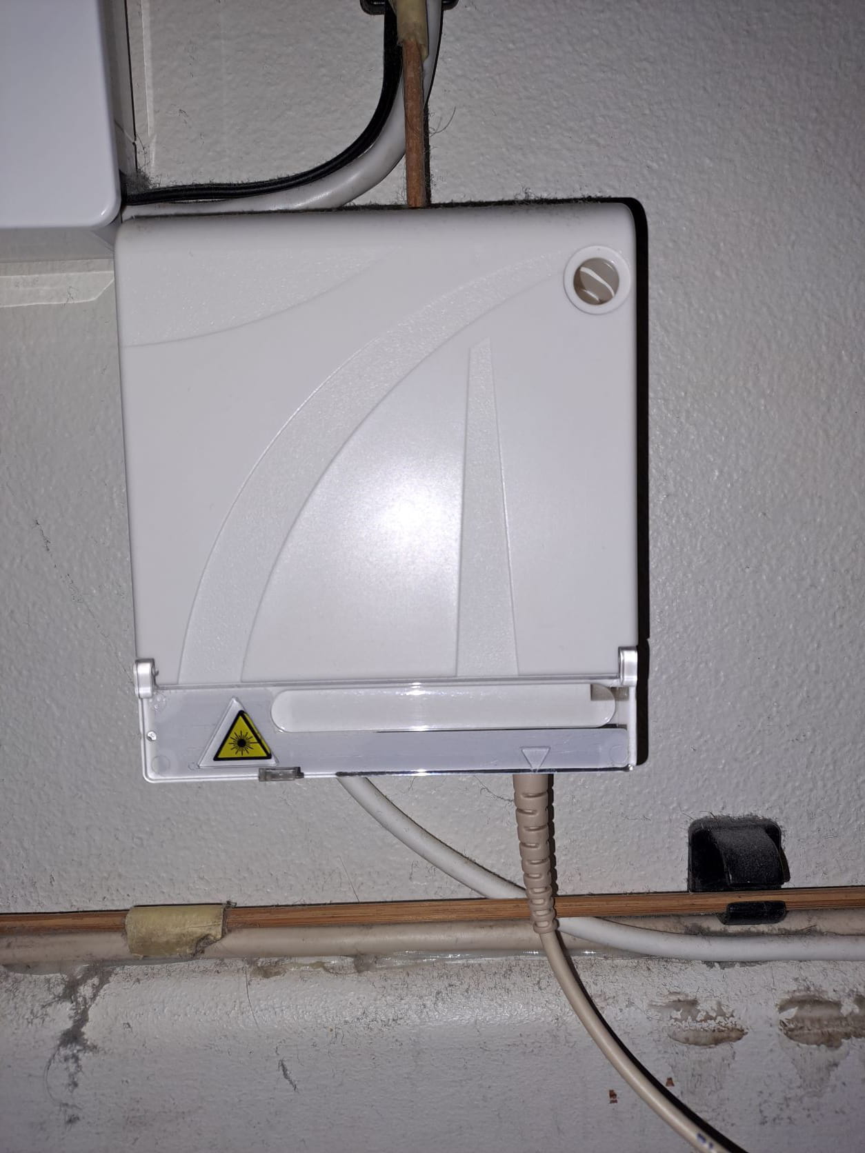
You can clearly see here the fiber coming from the previous RdCh box (connectivity?) And the FO cord going to the Box.
3 - Detail of the FO cable that connects the two Rdch/Floor boxes. It is significantly thicker than the one coming from the outside Garage Box.
Good evening
-
Re
In my mind, given its function, the ONT box = optical converter, required a 220v power supply (???), which I did not see when taking the photo.
If that's not the case, it suits me for my future installation.
Regards-
-
An ONT does indeed require a power supply
In fact, it's a second PTO.
A first PTO in the garage and then another optical cable goes to the second PTO.The PTO in the garage has essentially become just a junction box.
On the other hand, the one upstairs is indeed a PTO; here’s the same box:
Curiously, none of the PFOs have a standardized identification system, implemented by a label positioned on the subscriber's PTO box via a unique reference number.
Or there should be something like this on the arrival box:

Hello,
Thank you for all your feedback.I conclude that I can focus on the lacing that will connect these two future boxes.
I will start by passing a needle along the route that this lacing will take. On this occasion, estimate the tension (force to be exerted) that will be necessary for its pulling between the starting point and the endpoint.
Because I can imagine that there is more risk of rupture than with a 4-pair telephone line.
Have a great day.-
I have serious doubts that you will be able to pass a patch cord through a conduit if it is not of sufficient diameter. If I'm not mistaken, the connectors are about 8mm on each side (or 14mm diagonally) and 7cm long. There shouldn't be any too sharp turns.
Here’s something resembling what you posted in the photo
https://www.amazon.fr/Elfcam%C2%AE-Renforc%C3%A9-Monomode-Diam%C3%A8tre-Rallonge/dp/B08Z1MXVX7
and cheaper at the manufacturer https://elfcams.com/product/3689A remote PTO with a length of reinforced optical cable (between 7 and 30 or 50 meters) and optical connector.
This does not solve the issue of passing the connector through a conduit (they recommend a 20mm conduit) but offers a terminal PTO to be installed near your box. Once in place, there will be no more risk of fiber breakage between the garage and the floor unlike the simple patch cord that would connect directly to the box.
@ baladur 13
Thank you very much for everything.
I did a site inspection again. The existing duct under each roof section is a 16 mm IRO tube, with an interior measurement of 14 mm. And I only have one inaccessible 90° bend.
It might be a bit tight. But I'll give it a shot, as the economic stakes are relatively low—the price of a sacrificed cord :)
Best regards@baladur 13
The IRO tubes were "slipped" in a long time ago - and not without difficulties between the roof frame and the fiberglass insulation.
For a flexible 20mm duct, I don't even consider it.
I saw some hose ends at Boulangex today. It should work if I remove one or both of the current telephone cables (ADSL)
Note: the 90-degree elbow is at the exit of the IRO tube, BUT between two layers of fiberglass insulation.
I'll see.
Best regards
-