Ethernet frame
Solved
-
Hello,
I really have a hard time grasping certain concepts about the Ethernet frame, here’s what I know:

I know this by heart, but then when I come across an image that tells me this:

I’m a bit confused... why is there no preamble in this frame !! :(
And worse:

Here I’m completely lost, why are the @IP dst and @IP src found in this damned frame? This is not at all what I learned :/
Can you explain this to me?
Thanks in advance!
Best regards
N.
I really have a hard time grasping certain concepts about the Ethernet frame, here’s what I know:
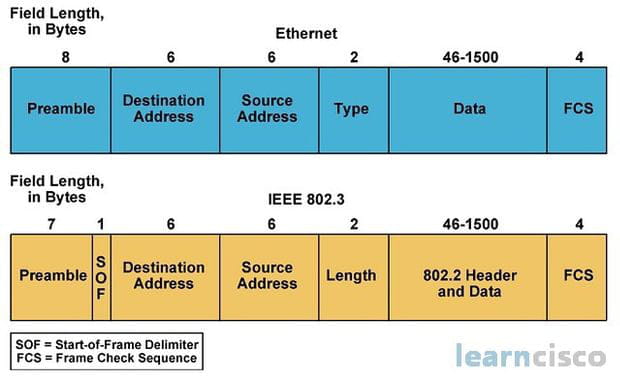
I know this by heart, but then when I come across an image that tells me this:

I’m a bit confused... why is there no preamble in this frame !! :(
And worse:

Here I’m completely lost, why are the @IP dst and @IP src found in this damned frame? This is not at all what I learned :/
Can you explain this to me?
Thanks in advance!
Best regards
N.
1 answer
-
Hi,
you will have to keep learning ...
The Ethernet preamble exists and is taught in courses, but you will never see it in a frame capture; it is fortunately removed by the network card, just like the CRC/FCS.
Anyway, if the FCS is incorrect, the frame is discarded and no one talks about it anymore.
The last diagram is wrong or too simplified, but it's true that you can see the IP addresses if there are any in a frame, by analyzing a bit further, then the TCP/UDP ports and other upper-level protocol data, if there are any; all that is in the data field of Ethernet/802.3.
You should install Wireshark and get an idea for yourself about decoding the different levels.
-
<hmm i="" think="" it="" my="" outlook="" that="" prevents="" me="" from="" understanding="" the="" osi="" model="" frames="" etc...="" really="" need="" to="" clarify="" in="" mind="" tell="" me:="" />Which physical device creates the segments (PDU layer 4)
Which physical device creates the packets (PDU layer 3)
Which physical device creates the frames (PDU layer 2)
And if I understood correctly from the courses I've seen online: segment < packet < frame (the frame contains the packet which in turn contains the segment) is that right? Or am I completely wrong?
Thank you for taking the time to respond! -
@Needix59The layers 3/4 are managed by the OS.
Layer 2 is managed by the network card for most functions, especially encapsulation, segmentation, and error control, and by the OS for some (ARP for example). -
-
@Needix59For segments or datagrams, not quite,
if they are well encapsulated in level 3 packets, they are often spread across several. -
Sure, here is the translation: Okay, this helps me a lot. Before writing this post, I thought it was the opposite (the segment that contains the packet that contains the frame), which is why I had difficulty with the online courses.
Thank you very much!
One last little question, and I'll leave you alone!
In the first image (above), we see the two types of frames used today. If I understood correctly, the packet is encapsulated in the "Data" part of the frame
and continuing with this reasoning, if it's an IP packet, the segment is encapsulated in the data part of the IP packet
is that right?
-