DTI, distribute internet via RJ45 with a distant fiber box
Odagirijoe
Posted messages
2
Status
Membre
-
brupala Posted messages 111934 Registration date Status Membre Last intervention -
brupala Posted messages 111934 Registration date Status Membre Last intervention -
Hello,
Here is my problem: I just moved into a new apartment that is wired with RJ45 outlets (after checking, it has 8 wires so it’s ready for the network?) in all rooms. The issue is that my fiber box and my router are in the living room, which is far from my DTI box that you can see in the photo below.

My question is simple: how can I correctly wire the box to deploy internet network in the rooms of my house? I specify that there is an RJ45 outlet in the living room, close to the router and I do not want (or cannot) put my fiber box and this router in the technical hatch where the DTI is located.
Thank you in advance for your advice!
Configuration: Macintosh / Chrome 93.0.4577.63
Here is my problem: I just moved into a new apartment that is wired with RJ45 outlets (after checking, it has 8 wires so it’s ready for the network?) in all rooms. The issue is that my fiber box and my router are in the living room, which is far from my DTI box that you can see in the photo below.
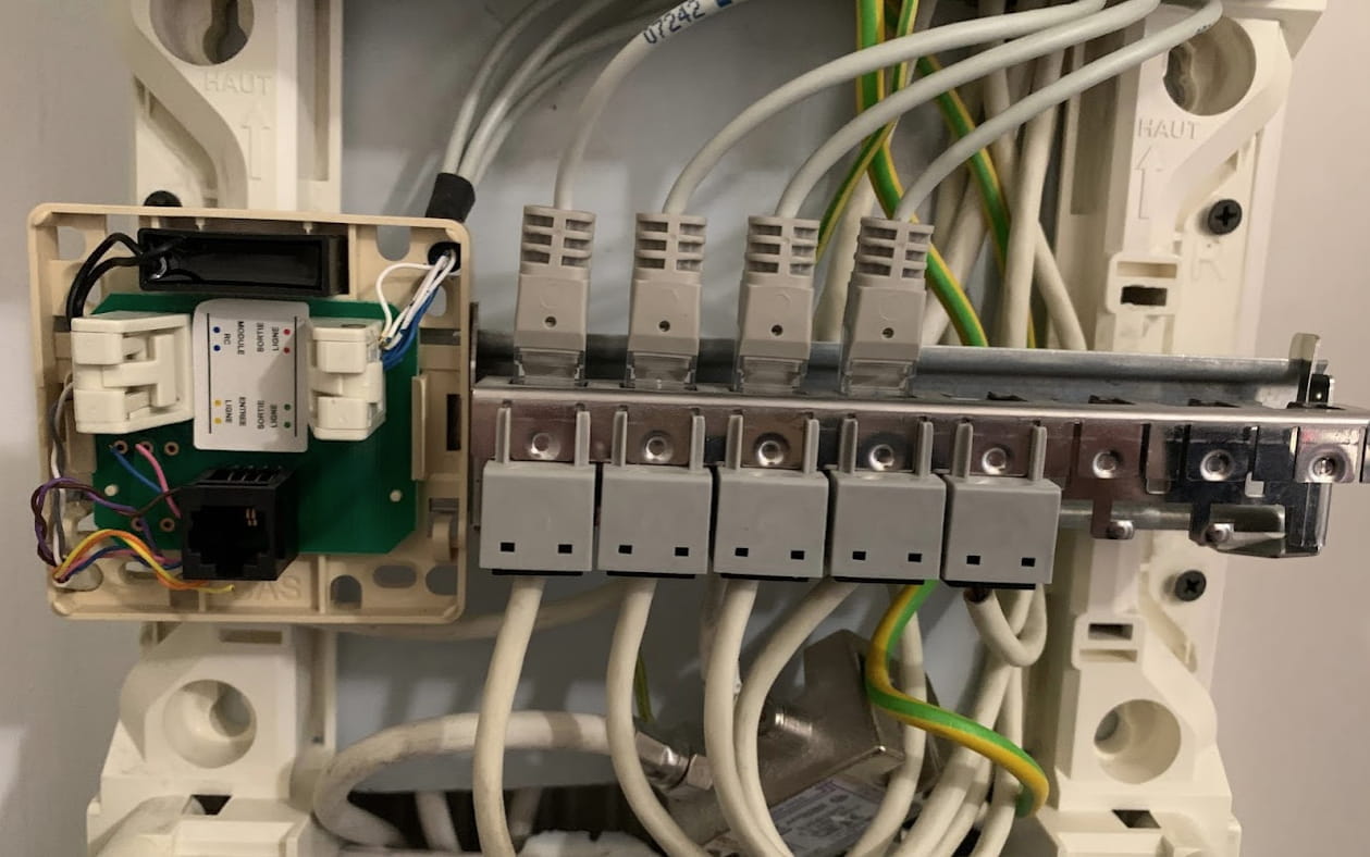
My question is simple: how can I correctly wire the box to deploy internet network in the rooms of my house? I specify that there is an RJ45 outlet in the living room, close to the router and I do not want (or cannot) put my fiber box and this router in the technical hatch where the DTI is located.
Thank you in advance for your advice!
Configuration: Macintosh / Chrome 93.0.4577.63
3 réponses

Hello,
The gray cables (octopus) connected at the top need to be removed, close the DTI, all this is only for telephony/ADSL and not for an Ethernet network.
You need to connect one output from the box to the wall socket. In the corresponding patch panel socket in the communication box, connect a switch with an Ethernet cable. This will allow you to multiply the Ethernet ports and with Ethernet cables connect the remaining 4 patch panel sockets, distributing Ethernet to all the wall sockets.
Example: https://www.amazon.fr/Netgear-GS208-100PES-plastique-connectivit%C3%A9-domestiques/dp/B00A33BY4A/
So if the 8 wires are connected to the wall and patch panel sockets, it should work without any further manipulation.
The gray cables (octopus) connected at the top need to be removed, close the DTI, all this is only for telephony/ADSL and not for an Ethernet network.
You need to connect one output from the box to the wall socket. In the corresponding patch panel socket in the communication box, connect a switch with an Ethernet cable. This will allow you to multiply the Ethernet ports and with Ethernet cables connect the remaining 4 patch panel sockets, distributing Ethernet to all the wall sockets.
Example: https://www.amazon.fr/Netgear-GS208-100PES-plastique-connectivit%C3%A9-domestiques/dp/B00A33BY4A/
So if the 8 wires are connected to the wall and patch panel sockets, it should work without any further manipulation.

quentin2121
Posted messages
9063
Registration date
Status
Membre
Last intervention
1 311
Basically, we connect the Ethernet switch somewhere on the DTI?
jee pee
Posted messages
9401
Registration date
Status
Modérateur
Last intervention
9 946
>
quentin2121
Posted messages
9063
Registration date
Status
Membre
Last intervention
Well, no, you read it very wrong! The DTI is not used in the case of a local Ethernet network. The DTI is the (open) box on the left. The RJ45 sockets (to the right of the DTI) make up the patch panel, each socket corresponds to the end of the cable from a wall socket.